Page 3 of 4
Re: DSP works!
Posted: Sat Nov 15, 2014 2:21 pm
by Tech_Marco
I could see that image here but I thought you said that it was done by another party. I mean to look at the picture taken by your machine, the worked that worked not good
Marco
Re: DSP works!
Posted: Tue Nov 18, 2014 12:28 pm
by bing1982
Had a bit of time to play with the laser today, and still not getting great results.
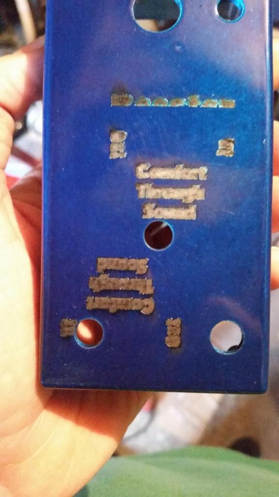
Marco - here is a picture of the text from my machine,as you can see, the paint between the letters isn't there for some reason. I've tried slower and faster speeds, stronger and weaker laser strength, but nothing seems to work. The font and text are the same size as the one on the black box that was done in a local laser cutting place.
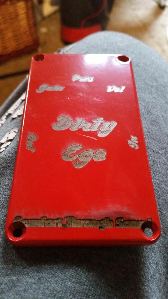
However, when the text is very slightly bigger, it seems to be ok.

But when I did it as part of a full label, all down at the same speed and power settings, the label is getting there, but the bottom bit is burnt and missing the paint between the letters. Again.
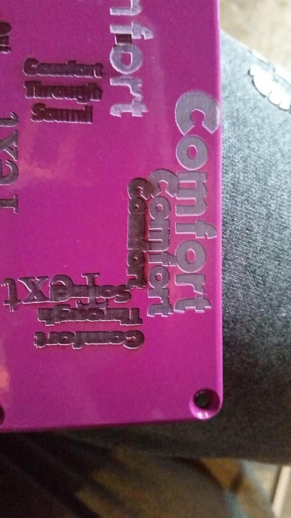
On this one, you can see the writing on the right hand side, the writing was all done at the same speed and power settings, when it gets below a certain size, it causes the same problem of burning and losing the paint between the letters again.
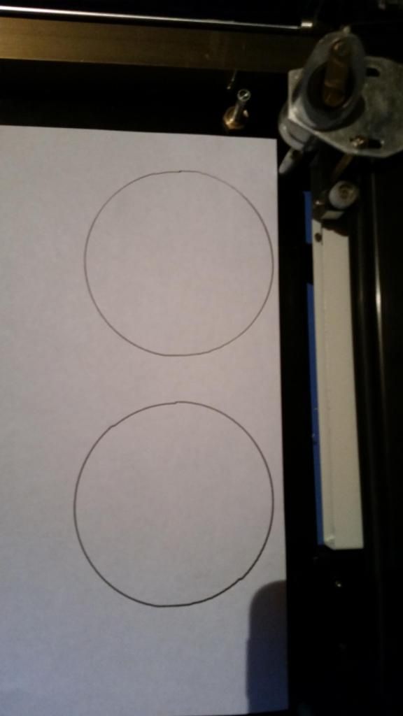
Also, with the circles, they still aren't right. The top circle is done at 100 speed, and you can see it's got a flat spot on it. The bottom circle is done at 50 speed, is a lot better, but at 10 o'clock and 4 o'clock, you can see notches or bumps in it. I've changed the rising edge and falling edge settings, got the focal point right, done the um value, and no I'm completely stuck on what to do next so any advice would be great,
Re: DSP works!
Posted: Tue Nov 18, 2014 3:01 pm
by Tech_Marco
I think you may having four issue:: 1) Beam alignment or focus 2) Belt or wheels may be damaged. Check the axis coupling see if it got lose 3) Bad motor 4) bad drivers
Marco
Re: DSP works!
Posted: Tue Nov 18, 2014 10:32 pm
by baccus61
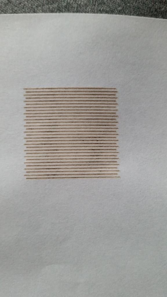
Draw a solid square 30mm big.
Set your lines per mm to about 1. We are trying to see if all the start and finish edges line up so we don't want all the engraved lines to be bunched up next to each other.
Engrave the square, not cut, on a piece of thick card stock that shows up the laser lines well at your preferred speed. You can try fast or slow to see what happens and any differences that may occur.
Look at the image and see if all the edges really do line up. If not then you have a problem with something being loose.
Rich.
Re: DSP works!
Posted: Tue Nov 18, 2014 10:34 pm
by baccus61
Check your belts for any damage to the teeth. You may have a bug stuck in between them or damage to some from some unforeseen thing.
If the engraved square gets lighter towards one side then you probably have an alignment or focus issue.
Make sure the table is the same height at either end of the axis as well. Sometimes, on my table, one of my drive screw bearings gets stuck and throws the table top out of flatness.
Re: DSP works!
Posted: Wed Nov 19, 2014 7:00 am
by bing1982
Thanks for the replies Marco and Rich.
I'll try and add some more information here, the picture in the previous post with the circles is rotated 90', no idea why, but the bumps in that circle happen everytime in exactly the same place.
Marco, I've done the beam alignment twice, but putting in a bit of cardboard at an angle, and then seeing where the smallest point is. Each time has given me the same result, and I've cut a bit of acrylic that measures the distance for me now, and I'm pretty sure that's correct. I've also checked the belts and wheels, and to the best of my knowledge, they look fine (I put a light on them and moved both the X and Y axis, and they all look fine, no damaged teeth on the belts or the cogs). I've also tried moving the X and Y axis frame, but it's bolted solidly to the chassis and doesn't have any movement from it being loose. I've got absolutely no idea on how to check the motors and drivers for any faults though.
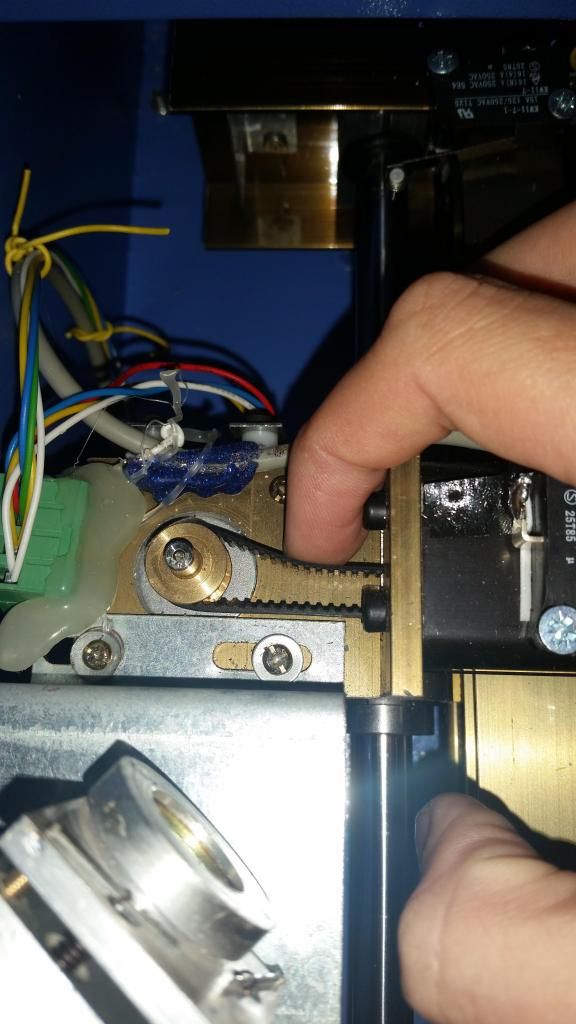
I've got a couple of pictures of the belt on the X axis (the one that goes left to right, that is the X axis isn't it?). As I've got no experience in these things before I started this project, I've got no idea if the belt is too lose or not.
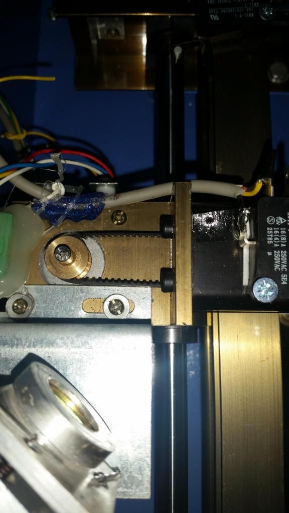
Rich, I've drawn a 30mm square, and set the engraving lines to 1mm, and I've posted a picture of the results below. I tried a few different speeds, and each time it came back with exactly the same results. Also, the lines furthest on the left is when the head is going from left to right, and the lines furthest on the right happen when the head goes right to left.
Re: DSP works!
Posted: Wed Nov 19, 2014 7:59 am
by acuralegendz
That belt looks to be loose
Re: DSP works!
Posted: Wed Nov 19, 2014 3:48 pm
by baccus61
Definitely a loose belt or pulley. All those line should have the same start and end point. That's why all your fonts look so wide/thick and squashed as the lines are so close together you can't see the start and end points of each successive line and it appears wider than it should.
No good setting up backlash in software either as it will happen at any speed and won't be regular so that won't help. That is a very good test to see what is going on with belts, focus, and general misalignment.
The belts should be tight enough so that they feel firm when pushed on but not tight like a guitar string. If too tight it will just wear out your belts too soon and put undue stress on your bearings. The one shown in the picture should only be able to be moved about 4mm to 6mm sideways. Your pulleys look like they are pressed on so that shouldn't be an issue unless one is loose in which case you will need to put a drop of loctite on it or replace it with a different one. ( but I doubt it as they are usually a pretty darn good tight fit)
It doesn't look like the focusing lens is very focused either. I would expect a lot finer line than 0.25 to 0.5 mm in width (just by looking at the pic). I reckon mine is about 0.09 in size or around 0.004 to 0.005 thou.
And yes, the sideways axis is commonly referred to as the X axis
Also with that style belt XL or MXL you have flat sides that want to ride up the sides of the pulley if loose and that is why I only use the HTD round profile belts now. All the photocopiers I have pulled apart for parts use HTD belts and they last millions of cycles and that's why I use them. I'm not saying to change the ones out on your machine, just that I don't think they are as good as round profile, so you need to keep them taught.
I bet you are learning a lot about the machine now, eh!

We all had to start somewhere and you are lucky all this laser stuff is around now and this great forum as well. When I built mine there wasn't much info around so it took me about 9 months of research and 3 months to build and about 4 months to get my original software sorted out. The LightObject combo is probably the best out there for the price/performance. I love it! The hardest part about the DSP is setting up the limits, page corner and start point as they can be anywhere depending on your machine. I had a real head scratch when adding mine and it probably took me 2 weeks to sort out. I'm not very analytical when it come to things like that.
You are in the same boat I think every one here on this forum has been in at some time so don't feel left out.
We are getting close to fixing it!
Rich.
Re: DSP works!
Posted: Thu Nov 20, 2014 5:02 am
by bing1982
Yep, I'm definitely learning a lot about the machine and how it works! When I was looking at getting a laser, all the UK ones are stupidly expensive, and the Chinese ones range in prices depending on the size and power. It was an absolute minefield trying to decide on which one to get, but I stumbled upon LightObject by accident through a Google search. I saw the DSP kit, had a look round the forum, and knew I had found the right option with a K40 with a DSP upgrade. As it's been my first time playing with a Laser, from doing test runs, I must say I'm extremely impressed with the DSP kit so far.
How do I go about tightening the belt? From what I can tell, I need to remove the X-Y axis as the belt runs under the X axis. With the HTD belt, if/when the current one wears out, I'll look into getting one.
With the focal point, I'll have a play around with it later, but I don't think the bet was set to the right height when I did the test, but I will double check it.
I'm going to go play with the laser now to see if/how I can tighten the belt up.
Re: DSP works!
Posted: Thu Nov 20, 2014 7:32 am
by waltfl
hi there
to tighten the x axis belt go thru the hole on the right side , there are two screws they are for tighten the belt so easy.
for focal point make the ramp test put a strip of wood in as long as the workarea then raise the right side about 1/2 inch and cut a line . then measure the distance between the surface of the wood and the head where the line is the thinnest, that's your right focal distance. the line should be as thin as a pencil line.
greetings
waltfl
bing1982 wrote:Yep, I'm definitely learning a lot about the machine and how it works! When I was looking at getting a laser, all the UK ones are stupidly expensive, and the Chinese ones range in prices depending on the size and power. It was an absolute minefield trying to decide on which one to get, but I stumbled upon LightObject by accident through a Google search. I saw the DSP kit, had a look round the forum, and knew I had found the right option with a K40 with a DSP upgrade. As it's been my first time playing with a Laser, from doing test runs, I must say I'm extremely impressed with the DSP kit so far.
How do I go about tightening the belt? From what I can tell, I need to remove the X-Y axis as the belt runs under the X axis. With the HTD belt, if/when the current one wears out, I'll look into getting one.
With the focal point, I'll have a play around with it later, but I don't think the bet was set to the right height when I did the test, but I will double check it.
I'm going to go play with the laser now to see if/how I can tighten the belt up.
Re: DSP works!
Posted: Wed Nov 26, 2014 2:23 pm
by bing1982
Waltfl - Thanks for pointing out what the hole was for! Just after i posted my last comment, I did a Google search and there was a picture of someone adjusting the belt with a screwdriver going through the hole. I always assumed it was for a light (I saw one laser cutter for sale with a light in that hole). I adjusted the belt tension, and it works! Circles are 100% round with the start and finish points lining up perfectly! However, only one tension screw was in, the other one wasn't attached to anything (it still isn't attached to anything, I'm going to try and get it in properly soon). I've got a LED strip, red dot pointer and air assist all wired up in the machine, just need to mount the LED strip more securely, and run the red dot pointer and air assist to the laser head.
I've done a lot of tests to see what power and speed settings I need, and I think I've found some that I'm reasonably happy with, although I do want to fine tune them slightly.
Also, I think there is some laser beam leaking out of the machine somewhere, and to protect my eyes I want to get some goggles, and doing a bit of research, it seems they come in rating for the wave length. Would I be right in thinking the wave length is 850 on these machines?
Re: DSP works!
Posted: Wed Nov 26, 2014 3:15 pm
by MitchL
bing1982 wrote:
Also, I think there is some laser beam leaking out of the machine somewhere, and to protect my eyes I want to get some goggles, and doing a bit of research, it seems they come in rating for the wave length. Would I be right in thinking the wave length is 850 on these machines?
No, 850 is more like the red dot. Co2 laser is 10600nm. You want glasses like these:
http://www.lightobject.com/CO2-10600nm- ... -P133.aspx
Or these:
https://www.thorlabs.de/thorproduct.cfm?partnumber=LG6
The thorlabs ones are slightly better (ODT 7+ vs ODT 6 for the LO pair).
I like my eyes, so I sprung for one set of Thorlabs that I wear during laser testing (my laser has no skins yet). I also have two pairs of the LO glasses that I'll wear even _after_ my laser has skins... just in case.
When you make the skin for your laser, consider putting a window so you can watch what you're cutting. You'll also want that to be laser-safe especially if you don't want to wear goggles while it's running:
I am using this in 1/8":
http://www.lasersafety.com/windows/lase ... dows/p5d05
Yeah, it's pricey. But as I said, I like my eyes.
Happy Thanksgiving!
/Mitch.
Re: DSP works!
Posted: Wed Nov 26, 2014 4:44 pm
by swamidog
slight correction:
the red is ~650nm, not 850.
MitchL wrote:bing1982 wrote:
Also, I think there is some laser beam leaking out of the machine somewhere, and to protect my eyes I want to get some goggles, and doing a bit of research, it seems they come in rating for the wave length. Would I be right in thinking the wave length is 850 on these machines?
No, 850 is more like the red dot. Co2 laser is 10600nm. You want glasses like these:
http://www.lightobject.com/CO2-10600nm- ... -P133.aspx
Or these:
https://www.thorlabs.de/thorproduct.cfm?partnumber=LG6
The thorlabs ones are slightly better (ODT 7+ vs ODT 6 for the LO pair).
I like my eyes, so I sprung for one set of Thorlabs that I wear during laser testing (my laser has no skins yet). I also have two pairs of the LO glasses that I'll wear even _after_ my laser has skins... just in case.
When you make the skin for your laser, consider putting a window so you can watch what you're cutting. You'll also want that to be laser-safe especially if you don't want to wear goggles while it's running:
I am using this in 1/8":
http://www.lasersafety.com/windows/lase ... dows/p5d05
Yeah, it's pricey. But as I said, I like my eyes.
Happy Thanksgiving!
/Mitch.
Re: DSP works!
Posted: Wed Nov 26, 2014 5:28 pm
by MitchL
swamidog wrote:slight correction:
the red is ~650nm, not 850.
Thanks for the correction -- 850 is infrared but you still want the correct glasses for CO2. I'd have protection ready even for "casual test firing."
/Mitch.
Re: DSP works! Re the ramp test
Posted: Fri Nov 28, 2014 6:25 am
by NickWL
When you've done the ramp test, cut a plywood (or whatever) 'key' such that you can rest a top edge on [any convenient part of the head assembly] and the bottom tip just touches the work surface. From then on you have a super-quick way of setting up your z-depth.


