Ah, when you said to redraw the image, I thought you meant when I change the parameters in LaserCAD, to redraw the square on the screen. I didn't realise it downloaded the original one on the laser and that would cause me the issues that I was having, and that the file needed to be deleted from the controller itself. It's my first time using a laser, so I suppose it was an easy mistake to make on my part.
I think the issue is that the paper is far too far away from the laser head, judging by videos that I've seen on YouTube. I'm going to test it now and hope that it the cause of my issue.
DSP works!
-
NickWL
- Posts: 252
- Joined: Mon Apr 07, 2014 2:23 am
- Contact:
Re: DSP works!
I find that regular re-aligning of the mirrors is a good rule - especially after a few days of frustrating fiddling when who-knows-what may have got knocked about!
-
baccus61
- Posts: 288
- Joined: Sun May 23, 2010 6:40 pm
- Location: Broken Hill, NSW, Australia
- Contact:
Re: DSP works!
Hi bing,
The laser head needs room to move each side of the job when it's engraving so if your boundary is past the home position or limits of the table then you will get an out of bounds error. The head needs room to get up to speed before it can engrave at the speed requested in the settings. I usually set my job up near the middle of the table so the head has heaps of room to move. Set the X to 30,000 and see how you go with that. Also try a small speed first, like 5mm/sec or 300mm/min.
My lasers sweet spot is 500mm/sec and any faster than that it actually gets slower in time due to the head having to go so far off the job to be able to ramp up to speed.
Check all the mirrors for alignment with a piece of cardboard near it and fire the laser with a small pulse starting from the first mirror and working your way through and use about 1/2 - 1/4 power . If you don't have a red pointer then you need to see where the laser is burning. Use a fairly thick piece of card so it doesn't burn through and discolour your mirrors and hold it just a little bit away.
Make sure the lens is focused properly. Bend a small length of cardboard to make a ramp with 10mm vertical side and sloping about 40-50mm to one side. Engrave a straight line at small power say 40mm along this ramp and you will be able to tell where your focal point is in the middle of the wide and thin points along the line. Easier to do than explain. I should make a video of this oneday.
That will get you started.
Don't forget to come back and let us know what it was that fixed it if and when you get it going. It all helps others get up to speed too and frees up Marco a lot so he doesn't have to sit here all day answering questions.
regards. Rich.
-
bing1982
- Posts: 31
- Joined: Mon Aug 25, 2014 6:47 am
- Contact:
Re: DSP works!
Nick, when I solved the problem I tried drawing the square, but only half of it came out! I knew it had to be the mirrors so I sorted that out, Took a little over 2 hours (the second mirror was quicker as I worked out how to adjust them properly by then and it's now cutting fine. Just need to set the focal length now.
Baccus61 - I solved the issue with the 'beyond size' message, I didn't realise the original square I drew was saved onto the DSP, then every time i adjusted the parameters in LaserCAD, it was still using the File on the DSP. All sorted with that issue now.
I've actually just come on the forum with regards to how to check the focal length, which you have already answered for me! Saved me searching for it
With regards to the 'um' value, i did the test, measured the square, entered the expected and actual value, put it into LaserCAD, and redrew the square, it was still 4mm out on one side, 5mm out on the other, so I redid the values in expected and actual, and it works fine now.
I'm still having issues with the Z table though. When I take the top of the blue frame off, and remove the black table, the spinning poles spin, however, with the black table and blue lid on, they don't move! Any ideas on what could cause this?
-
NickWL
- Posts: 252
- Joined: Mon Apr 07, 2014 2:23 am
- Contact:
Re: DSP works!
Yup: too tight!
The whole z-table assembly has to have plenty of slack in the drive train otherwise it just locks up when the motor puts tension on it. I put a thin (maybe 0.7mm) washer on top of each 'mounting' post and only did the top bolts up finger-tight.
Same with the drive belt: plenty of slack.
I actually re-made three of the four screw posts with the help of a retired clock-maker in the village - the originals all had a bit of a bend in them (not a reflection on LightObject, I bought this machine cheap as a reject 'second')
Bet this solves it!
Nick
-
bing1982
- Posts: 31
- Joined: Mon Aug 25, 2014 6:47 am
- Contact:
Re: DSP works!
Sorry for the slow reply, I've been away with work.
Last time I rebuilt the Z table as loose as possible and it worked without the table and top on it. I've now got the top completely off, and 2 of the stands that it sits on (only because an A4 sheet of acrylic wouldn't fit. I'll try rebuilding it very loosely tomorrow and see what happens. May even try some thin washers like you have done. I think yo have hit the nail on the head though, that I assembled it far too tightly.
Another question though, when I draw circles, They aren't round and have a flat bit on them where it looks like the Y axis isn't moving enough. Also, the start and finish of the circle don't match up. Would that be to do with the um value? First time I did the 100mm square, measured it, entered the actual value, it was still wrong. Ran the test again, entered the actual value, and it was better. I'm going to try it again tomorrow as I've found my digital calipers so I should get a more accurate measurement.
-
MitchL
- Posts: 71
- Joined: Fri Aug 23, 2013 4:40 pm
- Location: California
- Contact:
Re: DSP works!
That sounds like backlash to me. Most mechanical systems have some form of backlash - it is caused by slop/looseness in gears, timing belts, lead scews, or any place where motion is transferred.bing1982 wrote: Another question though, when I draw circles, They aren't round and have a flat bit on them where it looks like the Y axis isn't moving enough. Also, the start and finish of the circle don't match up. Would that be to do with the um value? First time I did the 100mm square, measured it, entered the actual value, it was still wrong. Ran the test again, entered the actual value, and it was better. I'm going to try it again tomorrow as I've found my digital calipers so I should get a more accurate measurement.
When you change directions in linear motion, it can take some amount of travel before the gears/belts/whatever engage on the opposite teeth.
For the types of mechanisms we use, you really cant get rid of it completely, but you can do two things:
- Try to keep the gears/screws/belts tight. Timing belts are actually pretty good already, so be sure they are reasonably tight.
- Make sure the hubs are attached securely to the stepper motors. If your motor has a flat side on the shaft, use it for the set screw. (for my homebrew laser, my motors did not, so I machined a flat).
- Enable software compensation if your controller supports it.
I'm about at this point on my homebrew build, my circles aren't' quite perfect either.
The way to measure backlash, if you have the right tools, is:
- Set a dial indicator to measure whatever axis you're looking at.
- Move the carriage in some direction a short distance.
- Zero the indicator (or record current value)
- Move the carriage a short distance (say 5mm) in the *same* direction that you just did above
- Move the carriage in the reverse direction 5mm.
- Read the dial indicator.
The amount on the indicator is your backlash. On the AWC608 theres a setting somewhere (I know I saw it) to enter backlash compensation. whenever the controller changes directions, it will send enough pulses to match your backlash compensation, removing the "dead space" between travel in one direction and another.
Two problems with this approach:
- You may not have a dial indicator.
- How do you move precisely 5mm using just the AWC608?
For that second one, I don't know -- you could probably adjust the amount of distance that the control panel arrows move the carriage and use that. I'm planning to send steps directly (disconnect the motors from the AWC608, use a SmoothStepper). If there is a way to manually move precise distances from the AWC608's control panel then all you'd need is a dial indicator.
/Mitch.
-
bing1982
- Posts: 31
- Joined: Mon Aug 25, 2014 6:47 am
- Contact:
Re: DSP works!
Thanks for the reply and help. I've spoken to the place where I bought the laser from and they said they tested the laser to make sure it was working correctly before they sent it out, and I've no reason to dispute this because there was still some water in the water tubes for the laser, but then again a belt tensioner may have been knocked during shipping or something.
As I haven't got any tools for measureing backlash, is there anything I could try? I've stumbled upon this thread here viewtopic.php?f=8&t=1590 and they look very similar to the circles that I'm producing. could that also be the cause? I've tried using google to try and sort the backlash and/or the servo tuning. I'm not having much luck and I'm still confused with it all.
As I haven't got any tools for measureing backlash, is there anything I could try? I've stumbled upon this thread here viewtopic.php?f=8&t=1590 and they look very similar to the circles that I'm producing. could that also be the cause? I've tried using google to try and sort the backlash and/or the servo tuning. I'm not having much luck and I'm still confused with it all.
-
MitchL
- Posts: 71
- Joined: Fri Aug 23, 2013 4:40 pm
- Location: California
- Contact:
Re: DSP works!
I adjusted the backlash in my machine a couple of days ago - I was able to do it with just the AWC and a dial indicator.
In LaserCad, there are some fields on the right side to manually move the carriage. So, you can do the
- Move towards the dial indicator 5mm
- Zero indicator
- Move towards the indicator another 5mm
- Move away 5mm
Then read the displacement on the indicator. Enter this under "Work Parameters."
My hobby machine had more backlash than I expected - 0.002" (0.0508mm) in X and 0.005" (0.127mm) in Y. I have a 2:1 reduction using timing belts, so this adds extra opportunities for lash. My circles look pretty good now.
Harbor Freight has cheap indicators: http://www.harborfreight.com/1-inch-tra ... r-623.html
They also have a set that includes an indicator stand.
I just clamped the indicator to the gantry. If your setup is different you can make a small bracket out of metal or 3D print to hold the indicator.
You could just cut circles and measure, but a direct measurement will give you better results.
/Mitch.
-
Tech_Marco
- Posts: 4658
- Joined: Mon Jun 15, 2009 3:00 pm
- Contact:
Re: DSP works!
Just make a squre box cutting say 100mmX100mm and measure the actual cutting dimension. If it is not 100mmX100mm, the use the built-in um calculator to get better value. Backslash seldeomat slow speed like 200 or 300mm/s
The other possibility is the Rising edge or falling edg setup on the motor driver setup. If it doesn't matched, it will show backslash symptoms
Marco
The other possibility is the Rising edge or falling edg setup on the motor driver setup. If it doesn't matched, it will show backslash symptoms
Marco
-
bing1982
- Posts: 31
- Joined: Mon Aug 25, 2014 6:47 am
- Contact:
Re: DSP works!
Ok, here is the update and where I am now.....
Marco - I redid the 'um' value test, and it's correct. I originally had to do the test a second time as the value for the Y axis was about (about a 4mm difference), but since then the um value has been fine. I've also just changed the 'falling egde' setting to 'rising edge' which has made an absolute massive difference, however, one side of the circle is a tiny bit jagged, but it is more or less round, and the start/finish points of it nearly line up now. It only seems to happen when both of the axis are moving together, when I've tried engraving, it works fine. But another issue has popped up. So far, I've been running it from my laptop, but now I've got a dedicated PC connected to it. It's only running Windows 7, CorelDRAW, and LaserCAD, but after doing anything that's needed, sending the file to the laser, then pressing the start button, anything I try to do after that makes LaserCAD crash, and even trying to close it down using control-alt-delete doesn't work, and the PC needs to be restarted. The program just completely stops responding. Also, using it from my laptop everything is the right way around, from the PC, everything is backwards, I know it's going to be a setting in LaserCAD, but I don't know which one.
MitchL - Thanks for advise on sorting the backlash, I've finally got a dial indicator (the first 3 I ordered from eBay never turned up, then I got one that offered pickup from a local shop). Unfortunately the Harbour Freight one is on the other side of the pond for me so I had to source another one. I've finally got some free time so I'm going to attempt to work out the backlash today, but the part where I enter the backlash settings is grayed out and won't let me enter anything, this is on my laptop though which currently isn't connected to the machine, is that why? I'll post back with my results shortly.
-
bing1982
- Posts: 31
- Joined: Mon Aug 25, 2014 6:47 am
- Contact:
Re: DSP works!
Update - I've sorted out why things were back to front, the Machine Zero and Page Zero were wrong. I'm still trying to find a good way to mount the dial indicator though. The boxes where I can enter the backlash are still greyed out, so when I do work out the difference, there isn't anyway I can enter them. I've uninstalled LaserCAD and reinstalled it, and it's still crashing, no idea why.
-
bing1982
- Posts: 31
- Joined: Mon Aug 25, 2014 6:47 am
- Contact:
Re: DSP works!
Latest update, still can't work out how to enter the backlash settings as they are still greyed out. LaserCAD still crashes everytime I try doing something after pressing the 'start' button. However, the issue is only on the PC that's connected to it, when I have my laptop hooked up, it doesn't crash, any ideas on how to solve it will be greatly appreciated.
For the circles, they are a lot better now I've changed the 'falling edge' to 'rising edge', but till not great. If I lower the cutting speed from 100 to 50, it's a lot better, but there are 2 notches on the circle, directly opposite each other, no idea why though.
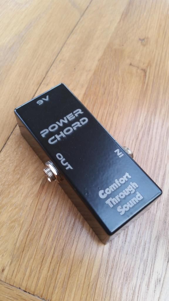
Also, I've got a slight issue with the engraving. When I've had some painted metal boxes done from a local place using their laser cutter, the lines appear between the letters and it's perfectly readable. However, on mine, the lines between the letters are non-existent, and the writing can't be read because of it. I've attached a photo of one that has been done by my local place, and you can clearly see the writing 'comfort through sound', but on mine it can't be read. I have noticed it does depend on which font is used, but I don't understand why the gaps between the letters aren't there.
I'm trying to play around with power and speed settings for the engraving, but without any luck, and any help would be greatly appreciated.
For the circles, they are a lot better now I've changed the 'falling edge' to 'rising edge', but till not great. If I lower the cutting speed from 100 to 50, it's a lot better, but there are 2 notches on the circle, directly opposite each other, no idea why though.
Also, I've got a slight issue with the engraving. When I've had some painted metal boxes done from a local place using their laser cutter, the lines appear between the letters and it's perfectly readable. However, on mine, the lines between the letters are non-existent, and the writing can't be read because of it. I've attached a photo of one that has been done by my local place, and you can clearly see the writing 'comfort through sound', but on mine it can't be read. I have noticed it does depend on which font is used, but I don't understand why the gaps between the letters aren't there.
I'm trying to play around with power and speed settings for the engraving, but without any luck, and any help would be greatly appreciated.

-
Tech_Marco
- Posts: 4658
- Joined: Mon Jun 15, 2009 3:00 pm
- Contact:
Re: DSP works!
I don't see your image. Can you post it
Marco
Marco
-
bing1982
- Posts: 31
- Joined: Mon Aug 25, 2014 6:47 am
- Contact:
Re: DSP works!
Strange, I can see the picture. I liked to it using the IMG tag from PhotoBucket. This link will hopefully work..... https://www.dropbox.com/s/9fio4cvq4uru7 ... 9.jpg?dl=0
I'll post a picture of what happens when I try the same font on my machine.
I'll post a picture of what happens when I try the same font on my machine.
Who is online
Users browsing this forum: No registered users and 4 guests